Relay Coordination Examples Excel


Protective Relay Calculations and SettingsPCS has extensive experience in the development of protective relay settings for transmission, distribution and generation systems, with voltage ranging from 480V through 500 kV. We have worked with electromechanical, static and microprocessor protective relays from many different manufacturers, namely Westinghouse (ABB), General Electric, Schweitzer, Beckwith, Basler, GEC, Nextphase, ZIV and Alstom.
The unit protection schemes is based on – the sum of the currents entering an area of the system must be zero.Any deviation from this must indicate an abnormal current path. In these schemes, the effects of any disturbance or operating condition outside the area of interest are totally ignored and the protection must be designed to be stable above the maximum possible fault current that could flow through the protected area.2. Non unit type protectionThe non-unit schemes, while also intended to protect specific areas, have no fixed boundaries.
The statements and opinions expressed on these websites are solely those of their respective authors and do not necessarily reflect the views, nor are they endorsed by Bioware, LucasArts, and its licensors do not guarantee the accuracy of, and are in no way responsible for any content on these websites, and the Star Wars: The Old Republic. Download game star wars battlefront pc.
As well as protecting their own designated areas, the protective zones can overlap into other areas. While this can be very beneficial for backup purposes, there can be a tendency for too great an area to be isolated if a fault is detected by different non unit schemes.The most simple of these schemes measures current and incorporates an inverse time characteristic into the protection operation to allow protection nearer to the fault to operate first. 2.1 Overcurrent protectionThis is the simplest of the ways to protect a line and therefore widely used.It owes its application from the fact that in the event of the current would increase to a value several times greater than maximum load current. It has a limitation that it can be applied only to simple and non costly equipments.2.2 Earth fault protectionThe general practice is to employ a set of two or three and a separate overcurrent relay for single line to ground fault. Overcurrent protection protects electrical power systems against excessive currents which are caused by short circuits, etc. Overcurrent relays can be used to protect practically any power system elements, i.e.
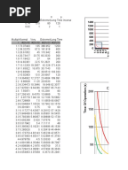
Relay Coordination Example
Transmission lines, transformers, generators, or motors.For feeder protection, there would be more than one overcurrent relay to protect different sections of the feeder. These overcurrent relays need to coordinate with each other such that the relay nearest fault operates first.Use time, current and a combination of both time and current are three ways to discriminate adjacent overcurrent relays.OverCurrent Relay gives protection against:Overcurrent includes short-circuit protection, and short circuits can be:. Phase faults. Earth faults. Winding faultsShort-circuit currents are generally several times (5 to 20) full load current. Hence fast fault clearance is always desirable on short circuits.Primary requirement of Overcurrent protectionThe protection should not operate for starting currents, permissible overcurrent, current surges.
To achieve this, the time delay is provided ( in case of inverse relays). If the interrupting rating is not properly selected, a serious hazard for equipment and personnel will exist.Current limiting can be considered as another overcurrent protective device rating, although not all overcurrent protective devices are required to have this characteristicVoltage Rating: The voltage rating of the overcurrent protective device must be at least equal to or greater than the circuit voltage. Inverse Time relays are also referred to as Inverse Definite Minimum Time (IDMT) relay. Inverse Definite Minimum Time (IDMT)The operating time of an overcurrent relay can be moved up (made slower) by adjusting the ‘ time dial setting’. It’s used when Fault Current is dependent on generation of fault not fault location.Normal inverse time Overcurrent Relay is relatively small change in time per unit of change of current.Application:Most frequently used in utility and industrial circuits.